
Vacuum Carburizing for Large Gear Applications-Stack Metallurgical Group
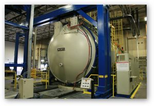
 Stack Metallurgical Group, quite possibly the largest commercial heat treater on the US West Coast recently released a “White Paper on Vacuum Carburizing of Large Gears” in which they do a very good job of explaining the advantages of vacuum carburizing as it pertains to large gears. Having one of the largest vacuum carburizing furnaces ever built anywhere in the world adds extra interest to the paper. The author of this report, Mr. Nels Plough of Stack can be seen in one of the pictures below where he is standing in front of a very impressive Ipsen bottom load vacuum furnace. To his right is Gord Montgomery and to his left Craig Beaumier and Mike Deaner.
INTRODUCTION
Increased demand for large, high precision gears requires specialized heat-treating equipment. In addition to size, exacting metallurgical requirements and repeatable process parameters affect furnace selection. Most large gears are processed in pit furnaces or large batch integral quenching furnaces. Vacuum carburizing had not been commonly used because large cross sections of most typical alloys cannot be effectively quenched with pressurized gas. Stack Metallurgical Group in Portland, Oregon installed a vacuum carburizing, oil quench furnace capable of processing large gears. Precise control of process gases, uniform heating, and process repeatability make vacuum carburizing an excellent choice for gear applications.
FEATURES
Seco-Warwick manufactured this two chamber, low pressure carburizing, oil quenching vacuum furnace. Load capability is 70” w X 70” d X 80” high, with a max total load weight of 10,000 lbs. Loads are suspended from a CFC overhead trolley, and are not set on an internal hearth. Processes are PLC controlled and are highly repeatable. The hot zone is insulated by 50 mm of graphite, allowing operating temperatures up to 1950° F, and producing furnace uniformity of ± 15° F from 1100°F to 1950°F. Process gases are introduced through mass flow meters, giving very precise control of the carburizing environment.

Quenching is done in a 9,500-gallon tank of oil. The agitation system was upgraded with four additional motors to improve oil flow and provide adequate heat removal for very large loads. Uniform fluid flow is critical so the entire load quenches evenly. During the quench, the entire furnace is under vacuum, so heat loss is minimal during load transfer, and surface condition of the parts is not degraded.
VACUUM CARBURIZING ADVANTAGES
 Vacuum carburizing is a non-equilibrium process that uses a series of boost and diffuse cycles to introduce carbon into the surface of a part. Process gas composition is very carefully controlled to match the requirements of each alloy and case depth. Intergranular oxidation, case uniformity and process predictability are advantages of this method.
Surface intergranular oxidation (IGO) is caused by oxygen present during the carburizing cycle. This creates defects at the surface which can be initiation sites for cracking (see Figure 2). Most standard practice requires a post heat treating operation in the root, typically grinding, or shot peening. Vacuum carburizing eliminates IGO. Air is pumped out of the furnace prior to heat up and carburizing, minimizing the presence of oxygen during processing. This results in higher integrity at the surface of the carburized case, and improved wear and fatigue resistance. Post heat treat machining or shot peening of tooth roots can be reduced or eliminated.
Vacuum carburizing provides excellent case uniformity for complex geometries. In a standard endothermic furnace, parts are introduced with carburizing gas present, and the furnace at a high temperature. As the load heats, the thin cross-sections of gears at the tooth tips reach carburizing temperatures well before thicker sections at the root.

This yields a wide variation in case depths across the tooth profile. During vacuum carburizing, the parts are heated to a uniform temperature before the process gases are introduced. As a result, multiple runs processed using the same set of parameters produced a very narrow range of case depths. A series of loads run with a case aim point of .100” had a spread of +.007” to -.005”, which is much less than standard endothermic gas processes (See figure). Gear root to flank case depth ratios are improved to as much as 90%, compared to conventional methods which achieve 65- 70% ratios. Higher strength at the root for a given flank case depth can help improve overall gear design or reduce heat treat process time for a given design requirement. In addition, high hardness can be maintained deep into the case.

Stack is currently using a simulation program for process development. All process parameters, including material chemistry, can be adjusted. A given case requirement can be simulated with numerous parameter changes before the first test load is performed. The results of the test can then be used to adjust the simulation, allowing the program to precisely predict outcomes for a given furnace and alloy. Process development for new alloys and case depths is shortened, improving heat treating lead times.
The furnace controls allow precise alloy specific process parameters. This yields consistent, predictable mechanical properties in the case, control of carbide presence and size and accurate control of carbon content. Improved consistency and control can result in improved fatigue resistance.
DISTORTION
Distortion control of complex parts like gears is the greatest challenge facing the heat treater. Symmetrical heating and cooling are critical to minimizing the movement of a part during processing. Residual stresses, alloy uniformity, prior thermal history and machining practices all contribute to the final outcome but are not controlled by the heat treater. Gear manufacturers can help decrease distortion in their parts by understanding how to reduce each of these factors prior to sending to their heat treater. However, process design, fixtures, furnace uniformity and quenching must be carefully considered and controlled by the heat treater to minimize or reduce distortion.
A unique feature of this furnace type is the elimination of the hearth. The load is suspended during processing, which provides both advantages and challenges. Fixture design allows the parts to contact the quench oil without creating excessive turbulence, providing very uniform quench flow and heat removal. Part specific fixtures provide the best opportunity to successfully quench a part. For example, flatness on a 32” diameter gear improved from 100” total to less than half that amount. Ovality was also maintained within very acceptable limits.
Size change is an unavoidable part of heat treatment. When a carburized gear is quenched and the material transforms to martensite (molecular structure of hardened steel), the volume of the steel increases in proportion to the carbon present. This causes a net size change that affects the overall distortion. If the part is carburized uniformly over the entire surface, the resulting distortion is minimized. Complex geometries like gears are difficult to uniformly carburize in conventional endothermic furnaces, so distortion can be greater.
SUMMARY
Complex part geometries operating in demanding environments require precise control of all aspects of heat treating. Using our vacuum carburizing furnace, these challenging parts can be given specific metallurgical properties and case hardness profiles, while minimizing the distortion effects associated with heat treating. From process development to fixture design, Stack can optimize the performance of your carburized parts.
Did you like this article? Click here to subscribe to The Monty.
View our recent magazines and podcasts by clicking the following link. https://themonty.com/magazine/
")