
The Heat Treatment of trying Tool Steels Part 5 By David Pye
Stress Relieving
During the manufacturing process of the tool, considerable machining stresses are generated on the surface. These stresses are known as induced residual stress raisers. Thus, the more the tooling is machined, the more induced mechanical stresses are generated.
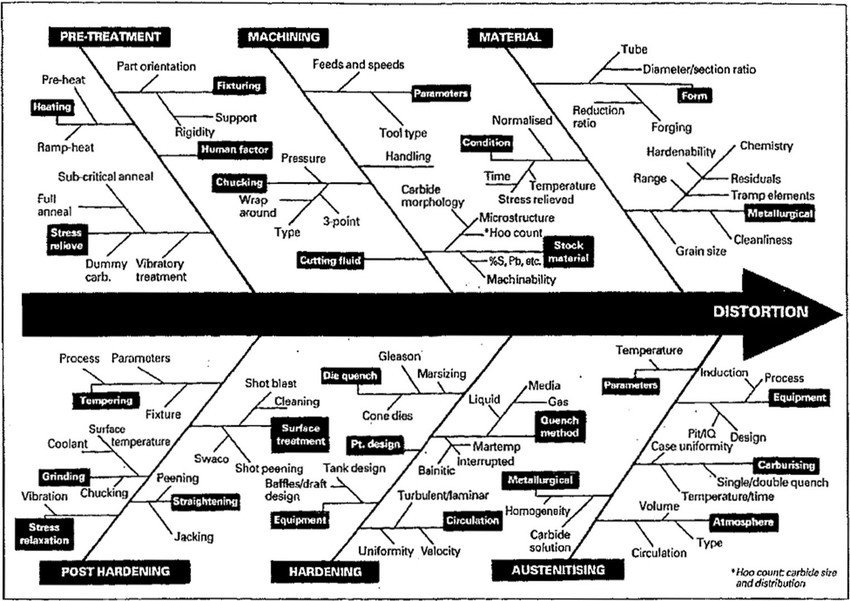
The induced residual stresses will only emerge with the application of heat. Thus, at final heat treatment, if the induced residual stresses have not been dealt with, then the residual stress will emerge at the final heat treatment. The next illustration shows a fishbone sketch of generated stress raisers during the manufacturing of the tooling.
In addition to the induced stresses, there may be the effect of potential cracking as a result of the induced stress in the steel. In some instances, and where surface compressive stress generated the compressive stress could have the potential to reduce the cracking.
In tooling manufacture, it is not uncommon to introduce residual stress relieving treatments during the machining and grinding operations during the manufacture of the particular tool.
It is also not uncommon to experience crack occurrences during the final grinding operations that are being applied to hardened and tempered tool steels with martensitic microstructures, or even to tooling that may have been work hardened during its operational life.
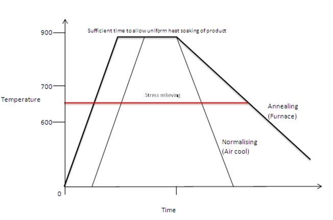
Those types of induced mechanical stress as the possibility of being the root cause of cracking during service. The Stress Relieve Temperature selection will be below the Indicted Red Horizontal Line
- Plain Carbon/Low Alloy Steels
- 550°C to 650°C
Do not underestimate the value if prior stress relieving before continuing to the final heat treatment procedure. It will reduce the potential for serious distortion.
Hardening of Tool Steels
This section will discuss the principles of heat treatment which will be followed by the principles of heat treatment of specific tool steel grades.The principal considerations that should be considered when preparing to harden and temper the particular tool steel grade and component for the final heat treatment is based upon;
Steel chemistry.
- Selection of the appropriate processing temperature in relation to the metallurgical requirement of the tool steel.
- The time of residence at the selected temperature.
- The events that occur when the steel transitions from room temperature to the selected process temperature, which determines the structure that the steel will orient itself into, and its phases, are known as transformation.
- The cooling rate must also be considered from the specifically selected process temperature.
- The final temperature (known as the tempering temperature) to enable the steel to be 'fit for service'.
Basic Principles of Hardening the Steel
A very simple description of steel is that it is simply a mixture of iron, plus a very small amount of carbon. That is as simple a description as can be made of steel.
In order to make the steel become hard, it is necessary to add small amounts of carbon. Carbon is the magic ingredient (so to speak) that will make the steel hard. However, the maximum hardness that the steel will accomplish will be approximately 62 HRC.
That will of course depend on the amount of carbon present in the steel. But it is necessary to make the steels do other things other than just become hard, and it is at this point that we will start to discuss the principles of making the steel become hard.
Basic Principles of Hardening the Steel
In this section you will gain an understanding of the Iron Carbon Equilibrium Diagram, the phases that the steel will transition through (depending on the amount of carbon present in the steel), its mechanical properties and the causes of these transformations.
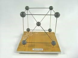
At Room Temperature the Iron exists in a 9-atom structure which is one on each corner and one located in the centre of the cube. This is known as a Body Cantered Cubic Lattice and will exist in this form up to approximately 720°C. as shown below.
This Illustration below displays the phase changes that occur in the Iron.
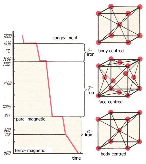
As you can observe the are three distinctive phase transformation occurrences. It should also be noted (as a very important observation) that each of the phases have a different volumetric size change. This simply means, that no matter what or how you heat up the iron, there WILL BE a size change. You have NO CONTROL over that phenomena.
Origin of Names of Phases
Ferrite is an area below the lower critical line of the Iron Constitution diagram and has a magnetic property. It comprises 9 atoms and is a BCC. (Body Cantered Cubic Lattice structure)
We now have added carbon (in controlled amounts at the steel making process), so now we have made steel!!! Depending how much carbon we add to the iron (in its molten condition), we can now determine what happens to the phase structure at various temperatures, with various carbon contents in relation the phase which will occur.
The following illustration shows the Iron Carbon Equilibrium Diagram. (Please be aware, that the diagram does not consider the addition of various alloys, only Iron and Carbon. For simplicity, one can make an equilibrium diagram with ordinary waters plus salt and noting the freezing point and boing point with different additions of salt into the water.)
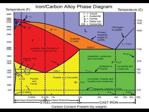
Hypo-eutectoid steels: Steels having less than 0.8% carbon are called hypo-eutectoid steels (hypo means "less than"). Consider the cooling of a typical hypo-eutectoid alloy along line y-y‘.
At high temperatures the material is entirely austenite. Upon cooling it enters a region where the stable phases are ferrite and austenite. The low-carbon ferrite nucleates and grows, leaving the remaining austenite richer in carbon. Hyper-eutectoid steels (hyper means "greater than") are those that contain more than the eutectoid amount of Carbon.
The Eutectoid line is that vertical line that separates hypo from hyper. It is generally found at a point of 0.77% on the horizontal carbon axis line. When such a steel cools, as along line z-z' , the process is similar to the hypo-eutectoid steel, except that the primary or pro-eutectoid phase is now cementite instead of ferrite.
Various phases that appear on the Iron-Carbon equilibrium phase diagram are as under:
- Austenite
- Ferrite
- Pearlite/Cementite
- Martensite
Ferrite
Ferrite is known as α (Alpha) solid solution. It is an interstitial solid solution of a small amount of carbon dissolved in α (Alpha) (BCC) iron. It is a stable form of iron below 912°C. The maximum solubility is 0.025 % C at 723°C and it dissolves only 0.008 % C at room temperature. It is the softest structure that appears on the diagram.
Ferrite Properties:
Tensile strength = 40,000 psi;
Elongation = 40 % in 50mm;
Hardness > Rockwell C 0 or Rockwell B 90
Cementite
Cementite or iron carbide, is a very hard, brittle intermetallic compound of iron & carbon, as Fe3C, contains 6.67 % C. It is the hardest structure that appears on the diagram, exact melting point unknown. Its crystal structure is orthorhombic. It is/has;
- A low tensile strength (approx. 5,000 psi).
- A high compressive strength.