CFC Fixtures – the Guarantee of Added Value in Heat Treatment
Dr. Rolf Terjung, founder and CEO of CFC fixturing company Graphite Materials provides us with this excellent article about why CFC racks make so much sense in heat treating applications. https://www.graphite-materials.com/?lang=en
CFC racks have established themselves today in the various heat treatment processes. An essential prerequisite for this is reliability, which is ensured, among other things, by the predictability of the loading conditions and the reproducible material production. Basic design principles have been predestined over the years. The customer benefit lies in the significantly higher added value compared to the cast steel devices and consists of: More components per batch (turnover), increased process reliability, automation, additional furnace capacity and lower workload. As a result, the higher acquisition costs are amortised already after 18 months, depending on the component. Different designs for “horizontal”, “vertical” or “hanging” batching are used.
Devices: materials in competition. Why have CFC fixtures become established in the competition against heatresistant steels/cast steel? For effective heat treatment, devices are imperative to improve process reliability, workpiece quality, shorten process times and reduce costs [1] to list just a few fundamental reasons. Devices made of steel are still widely used with their challenges that are known:
• dimensional and shape changes,
• heavy weight,
• short lifespan (growth, embrittlement).
In the mid-1990s, with the support of research, the industry began to test and evaluate CFC (Carbon Fibre-Reinforced Carbon, CFC Fixtures – the Guarantee of Added Value in Heat Treatment CFC racks have established themselves today in the various heat treatment processes. An essential prerequisite for this is reliability, which is ensured, among other things, by the predictability of the loading conditions and the reproducible material production. Basic design principles have been predestined over the years. The customer benefit lies in the significantly higher added value compared to the cast steel devices and consists of: More components per batch (turnover), increased process reliability, automation, additional furnace capacity and lower workload. As a result, the higher acquisition costs are amortised already after 18 months, depending on the component. Different designs for “horizontal”, “vertical” or “hanging” batching are used. Keywords CFC fixtures, near-net-shape positioning, alumina fibres, loading condition, calculation, added value, distortion, reliability.
Carbon Composites C/C) as a new fixture material in the competition against heat-resistant steels (over 750 °C) [1]. The requirements for the “ideal”” material for hardening devices were defined as follows [1]:
• high temperature resistance (absolute and gradient),
• high mechanical strength (σTensile, σBending, σCompression, Youngs-Modulus, Ductility) with low density (ρ),
• good chemical resistance to atmospheres, quenching media, washing media and the material to be hardened,
• high dimensional and shape stability at high temperatures (CTE low, “λ” high, cp small),
• good workability,
• low costs (material, machining, longevity, no rework, no levelling),
• large variety of shapes/designs: tubes, bars, grids, plates,
• high delivery performance.
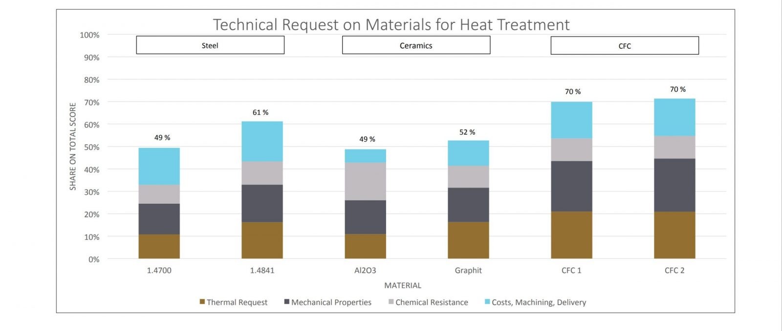
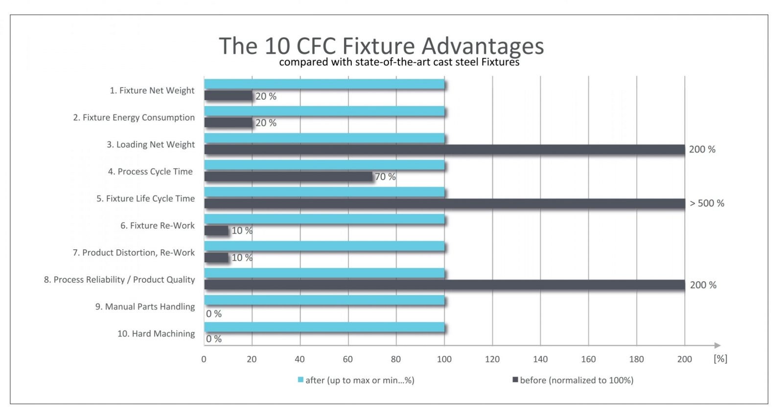
Heat-resistant steels (standard), technical ceramic (engineering or high-performance ceramics), graphite (ceramic) and fibre composite materials (CFC) were evaluated as suitable materials in a matrix. CFC proved itself to be the optimum material. The experience gained so far with CFC racks compared to cast steel in the various heat treatment processes (tempering, surface hardening, nitrocarburizing, brazing and sintering) is rated in Fig 2.
The ten CFC-fixture and rack advantages (min./max. values of the bars depending on customer situation and investment volume; non-binding; by experience). The requirements for the “ideal” material CFC stand out in this illustration. An example from industry (automotive parts) makes the difference clear in absolute figures. [3]. The device weight could be reduced by 62 % and at the same time used for more components by means of new positioning. Only the furnace capacity of 1500 kg can be “sold”. The decisive factor for value creation and thus also for amortisation is the approximately 90 % increase in the number of parts per furnace cycle (turnover = quantity x price). The furnace utilisation (max. 1500 kg) could be almost doubled with components, from 43 % to 80 %. The process time remained almost unchanged. Acceptance through reliability CFC devices have become established in the various processes, but still not to the extent that the advantages (Fig. 2) suggest. Due to the density (CFC: 1,6 g/cm³/ steel: 7,9 g/cm³) there is a weight advantage of approx. 60–80 % for CFC, as is shown in Fig. 2. The fixture can be made to be comparatively “slim”. If a filigree-looking CFC and a “massive” steel rack with the same load-bearing capacity are placed side by side, the load-bearing capacity is
obviously questioned. The calculation of the rack load-bearing capacity for standard and special constructions is an essential prerequisite for customer acceptance. Well-honed manufacturing processes for the mass production of CFC today guarantee reproducible material parameters (material data sheet) for engineering (materials technology – design – simulation – production) [4]. In-house market research on heat treatment furnaces revealed two main grid dimensions:
• 600 mm x 500 mm (500 kg);
• 900 mm x 1200 mm (to 1500 kg).
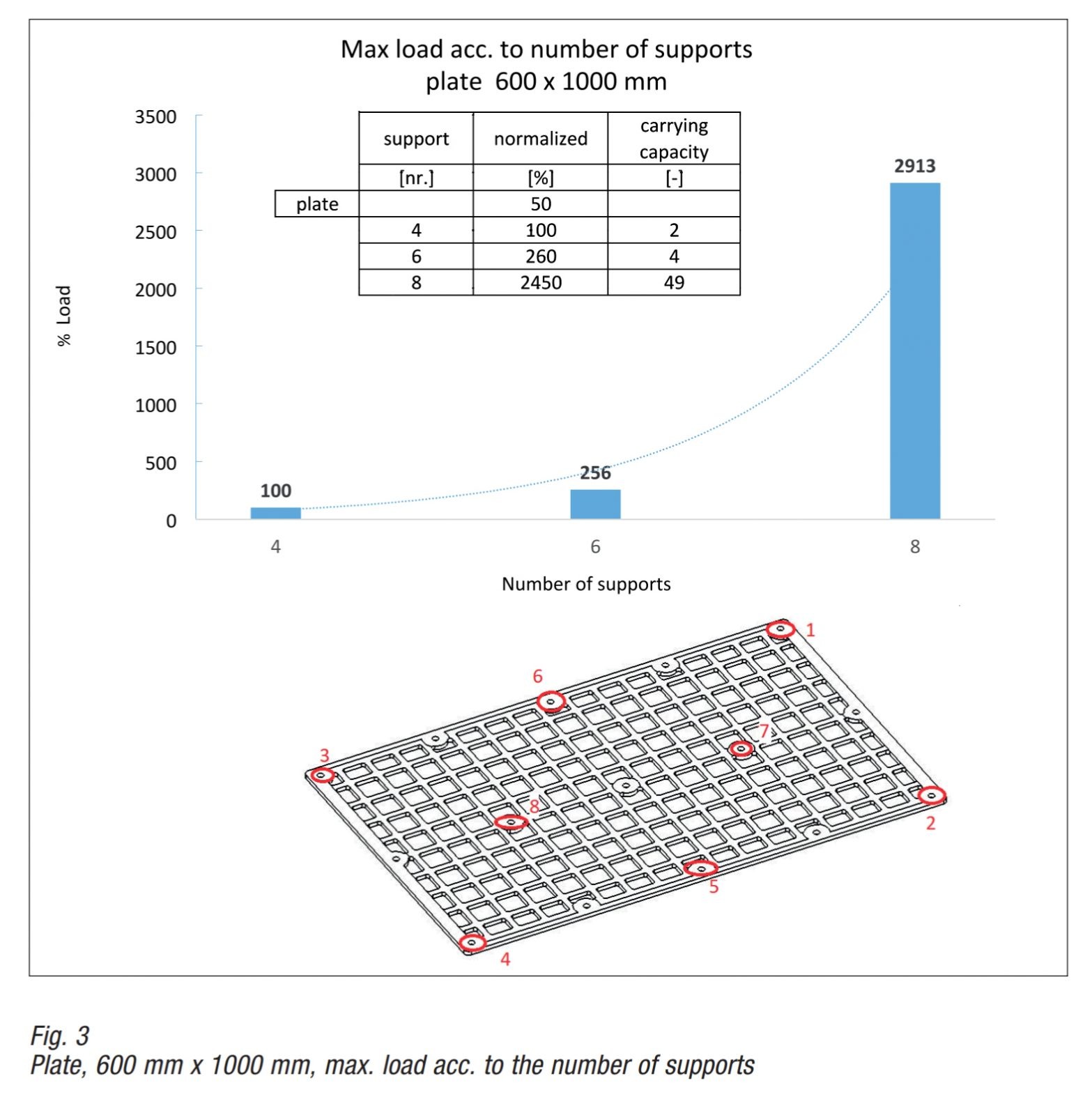
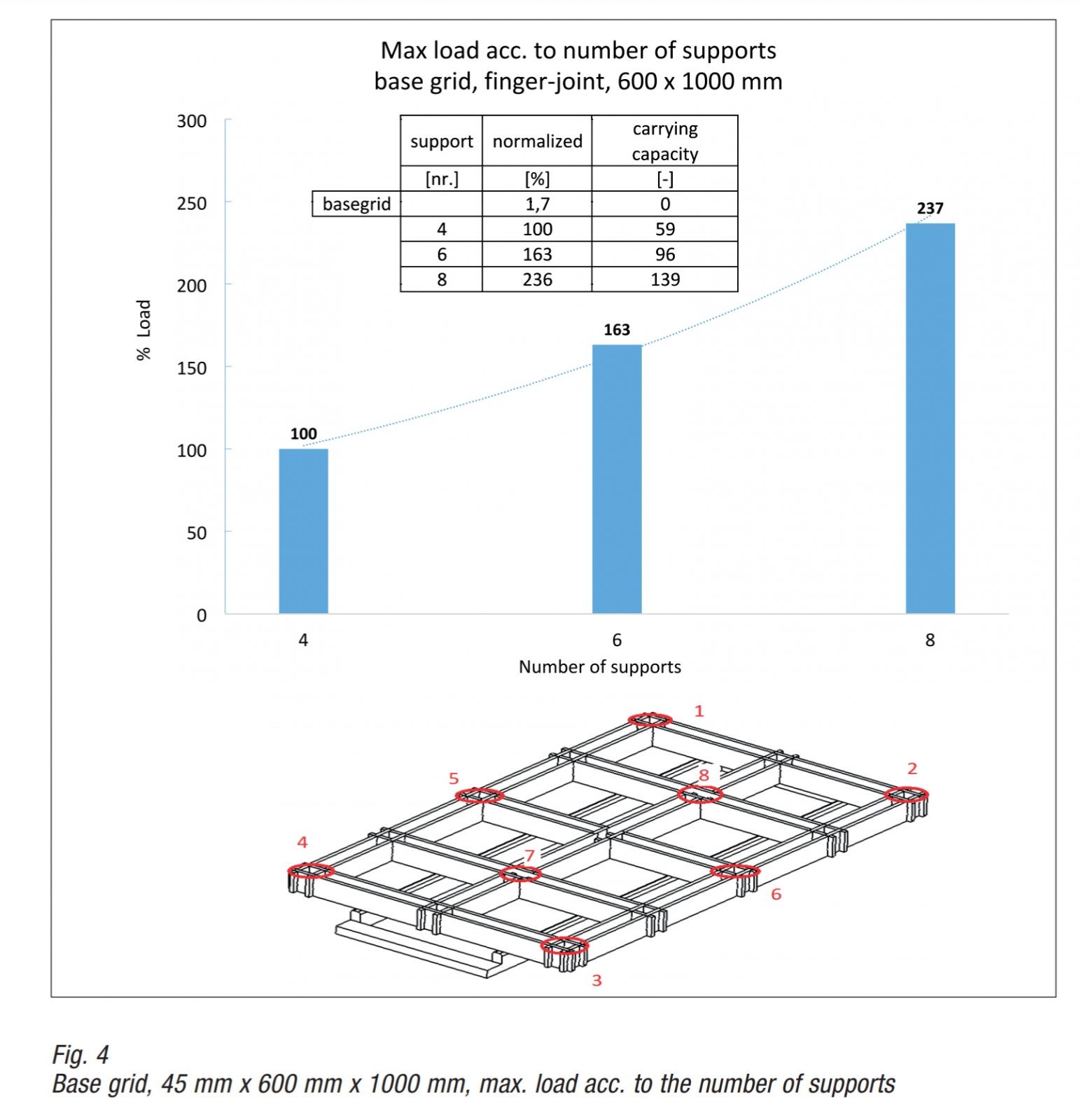
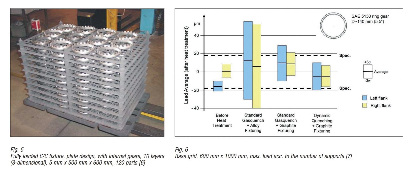
The furnace chamber capacity is between 500–1500 kg, with special sizes that can be both smaller and larger. The mechanical loading condition can be calculated with high accuracy for the frequently used “horizontal” component batching. The material data used refer to a unidirectional CFC with pitch matrix. The continuous fibres are each offset by 90° in the superimposed levels (0°/90° layer structure). The results presented for a plate and finger-joint design are based on an FEM analysis (Finite Element Method). The deflection value for both, plate and base grid, is set to minimise the component distortion. The load capacity (parts load in [kg]) was standardised on 4 supports (100 %). The number of supports for this dimension is usually 6. The load capacity is approximately 5 times the weight of the plate. Two additional supports (net weight 70 g/support) increase the load capacity 50-fold. The matching base rack (fingerjointed slats, Fig. 4) with the same number of supports carries 630 kg, which is approx. 100 times its own weight. The loading condition is designed to be supported by the transport fork (transport and batching). This requirement must be met in the furnace or a beam support along the three longitudinal connectors (1000 mm) outside-centre-outside (standard). The calculation is carried out for the loading condition at room temperature. CFC materials have the advantageous characteristic that the strength increases with increasing temperature. At process temperatures of 1000 °C the values are approx. 10–15 % higher than at room temperature [4]. The calculation approaches have proven themselves through industrial experience. These simulations are extended to the most common rack designs in order to increase the benefit/cost advantage further through a “standard design”. The load becomes “calculable” and with industrial experiences a guarantee for process reliability. Component distortion is controlled by near-net-shape component positioning The greater the surface/volume ratio for a component, the higher the likelihood of component distortion. Mastering the dimensional and shape tolerances becomes more difficult. The further development of the heat treatment process has achieved considerable process advancement e.g. in vacuum heat treatment. Highly stressed components in automotive, mechanical and plant engineering are now case hardened in many cases by Low-Pressure Carburizing (LPC) with high pressure gas quenching (HPGQ) [5]. Fig. 5 shows a “horizontal” batch of ring gears on plates. A batch consists of two stacks (side by side), each with 10 layers stacked on top of each other (500 mm x 600 mm) [6]. The influence of the “steel” and “CFC” device materials on the component distortion is shown schematically in Fig. 6.
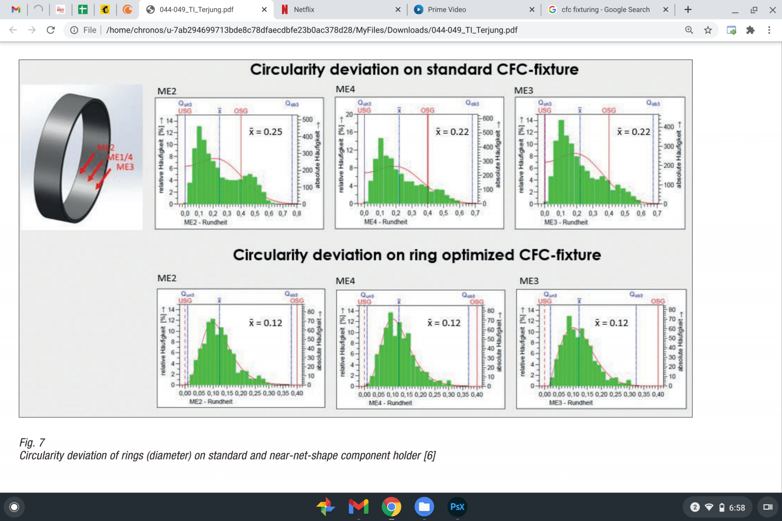
The shape deviation is reduced considerably when batching with a CFC device and can also be further improved by process optimisation (dynamic quenching). Due to the low CFC expansion coefficient (CTE: CFC 1 to steel 12·10-6/K) the component (steel) can “grow” relative to the device (Temperature T k) and “shrink” (T m). With reference to Fig. 2 the 6th advantage “Fixture Re-Work” and 7th “Product Distortion, Re-Work” are clear with this example. In recent years, single-layer batching (2-dimensional) has been established to master component distortion [5]. The heating and cooling process can be carried out evenly and process-induced stresses can be minimised. The influence of the near net-shape component position on the CFC device with regard to the roundness deviation of a thin-walled ring is shown in Fig. 7. The rings were initially evenly distributed on a plate (loose and without contact). Due to the near net-shape positioning, the maximum values of the roundness deviation could be reduced by 25 % to
0,3 mm and the mean deviation by 50 % to x¯ = 0,12 mm. Rejects were reduced to almost zero. Process reliability and product quality improved tremendously (Fig. 2, 8th advantage). The examples clearly show that only by the exchange of information with the customer a device can be tailored to the component meeting the technical requirements. It is useful to draw up a specification (customer requirements questionnaire) to define the process conditions and rack criteria [6]: Process conditions:
• vacuum, atmosphere (contains oxygen?),
• pre-oxidation (temperature-level),
• process temperature (contact reaction),
• furnace capacity (max. loading [kg]),
• batching (horizontal, vertical, hanging),
• loading and unloading (manual, automated).
Fixture criteria:
• component cross section (bulkiness),
• distortion criteria (dimensional and shape tolerances),
• shape and position of the component position (contact surfaces component – device, shading),
• flow through (heat flow),
• loading density (parts per batch),
• load capacity,
• positioning accuracy.
Restrictions and countermeasures
In addition to the proven advantages of CFC material, there are also restrictions that limit its use, particularly in air and oxygen-containing atmospheres. It is recommended to assess the following three aspects for each application:
• Reaction with oxygen (O2): an oxidising reaction occurs in air or oxygencontaining atmospheres above 350 °C [2]. Carbon (CM) from the matrix “burns” with air-oxygen (O2) to form carbon dioxide (CO2). In the presence of water vapour (H2O), matrix carbon oxidises above 700 °C to CO or CO2 with the elimination of hydrogen. Preoxidation processes must be adapted to this limitation.
• Reactions with steel: above 1000 °C (vacuum, inert gas) contact reactions can occur in the form of discoloration, unwanted carburization or even local melting (eutectics) [2].
• Reactions with media: adsorption of liquid media (quenching oils, washing media) via the open porosity and the rack design.
Oxidation in air can only be prevented by temperature. CFC racks should not be used in air above 350 °C. Different impregnations and coatings are successfully used in atmospheres with very low oxygen concentrations. Pitch-bonded (matrix) CFC qualities with comparatively high densities (1,6 g/cm³) are advantageous because of the graphitic structure. Graphite is less reactive than carbon (amorphous) to oxygen and other media [8]. The contact reactions with steel can be reliably prevented by a mechanical separation. For this purpose, various components made of aluminium oxide (Al2 O3 ) fibre ceramics have proven themselves in recent years. Various solutions for process temperatures above 1000 °C (vacuum, inert gas) have been developed under the brand name DuComGrid® = Dual Composite Grid [4]. According to the author’s knowledge, industrial washing processes (<90 °C) with fat-dissolving media, also in connection with ultrasound support, have no damaging effect on the CFC material. If quenching oils (gas carburizing with an oil bath) are used to cool the batch, the batch temperature (furnace outlet) should be significantly below the flash point of the oil in order to avoid self-ignition (flame formation, oxidation >350 °C). After a few treatment cycles (<10), the oil intake stops [2]. Oil build-ups form residues in the subsequent “tempering” (150–300 °C) and fill the open pores. In addition, the “running off” of liquids can be made easier by constructive measures in order to minimise build-up.
Potential and outlook
The device is mandatory because the components for heat treatment must be batched. The component achieves added value and the costs of the process are therefore reduced. CFC racks increase added value and at the same time reduce costs, as the “10 Fixture Advantages” make clear. Well-honed manufacturing processes ensure reproducible material parameters, which enable a reliable calculation of the load configuration. Impregnations and coatings permanently minimise the reaction with residual oxygen and increase the rack service life. In the future, further improvements can be expected here. Aluminium oxide fibre ceramics in a CFC rack can exclude the contact reaction to the work piece. By means of Additive Manufacturing (AM), near-net-shape contact points can be pressed from ceramic and integrated into the rack in a form-fitting manner. This gives the design additional freedom, which helps to master the dimensional and shape tolerances. The processing is carried out using proven technologies (turning, milling, water-jet-cutting), and the raw material base (matrix [phenolic resins/ pitches] and fibres) is set up ready for delivery. The advantages of the CFC device are different but measurable for each user in the evaluation: more parts per furnace cycle, with reduced reworking due to less warping, increase turnover (quantity x price). The automatic loading contributes to the quality and the service life and to the investment costs. All advantages reduce process costs, shorten amortisation and increase added value. The calculation approaches are refined further, because the increasing degree of individualisation of components requires not only the “special solution” but also the competitive “customisation” for small series.
Did you like this article? Click here to subscribe to The Monty.

