Advantages of CFC Fixtures When Case Hardening In Automotive Application
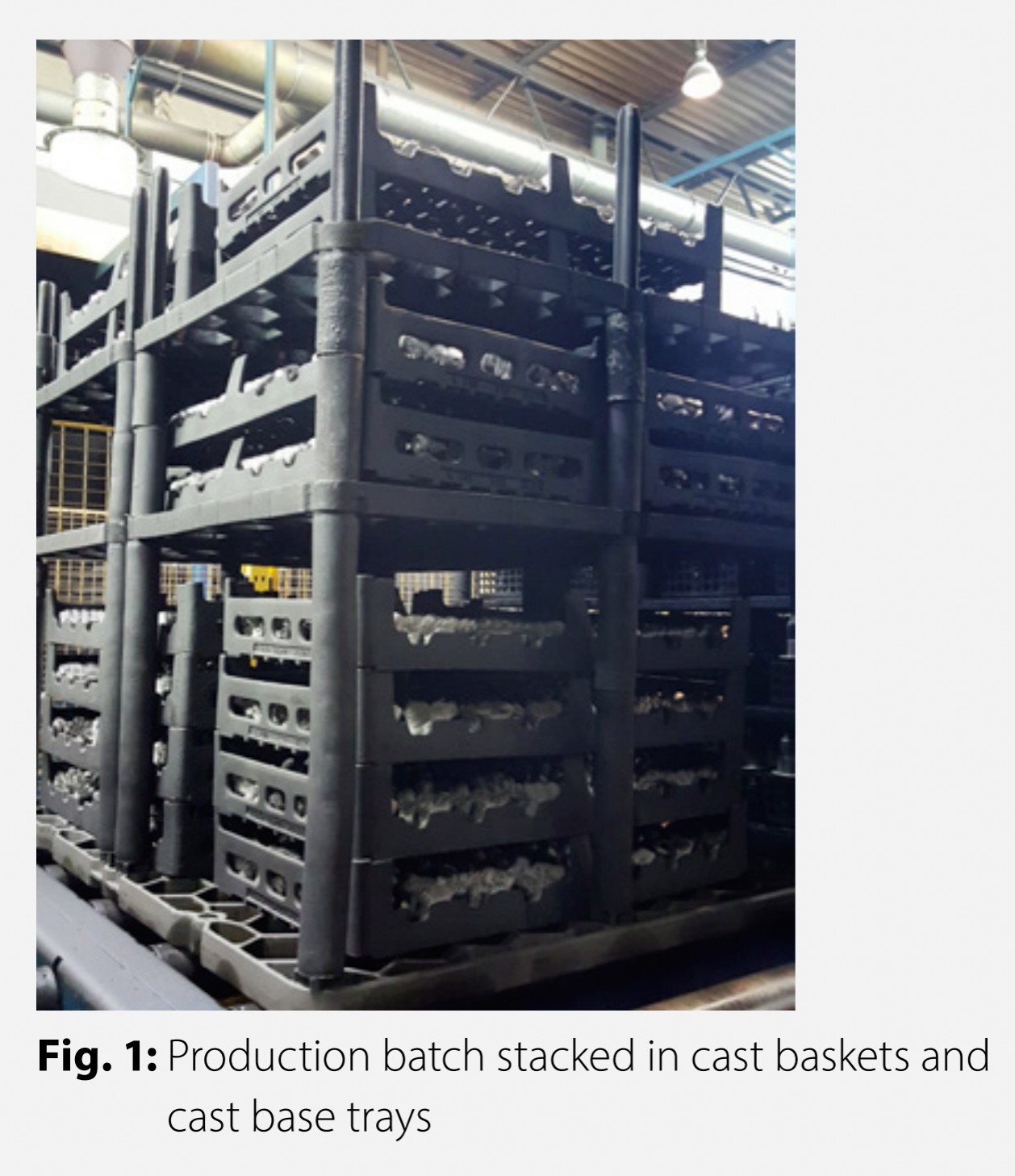
The drive component cited in this article is case hardened in a multi purpose chamber furnace. The surface/weight ratio is low and characterized by a solid cross-section in different sizes. Component distortions due to heat treatment are thus less critical and are not considered further. The largest component weighs about 500 g. Components are loaded in cast baskets, which are positioned on cast base trays (Fig. 1).
The existing production capacity is to be made available in full for the current order volume without additional plant investments and customer delivery dates are to be met. Production will take place in three-shift operation 7 days per week. A furnace campaign takes about 10 h and is limited by the weight of the maximum load capacity of the system of 1,500 kg. The cast loading systems used cannot increase the furnace capacity in pieces/batch. Based on experience gained internally with CFC (CFC = Carbon Fibre – reinforced – Carbon), a corresponding CFC fixture system is preferred. Compared with a cast fixture, the mass of the CFC fixture can be reduced significantly and this enables a larger number of components per batch (packing density); furnace loading with a maximum total mass of 1,500 kg (fixture and components) remains the decisive criterion.
CFC ASSESSMENT
Specific examples were used in [1] to demonstrate the advantageous properties of CFC workpiece fixtures for drive components with low-pressure carburizing and subsequent gas quenching. For the application described in this article, the following advantages support the use of a CFC system [2]:
■ Higher loading (components/batch) thanks to slim design (spec. strength [strength/bulk density])
■ Employee-friendly loading and unloading
■ Long service life of the fixture (no distortion of the fixture due to creeping/embrittlement).
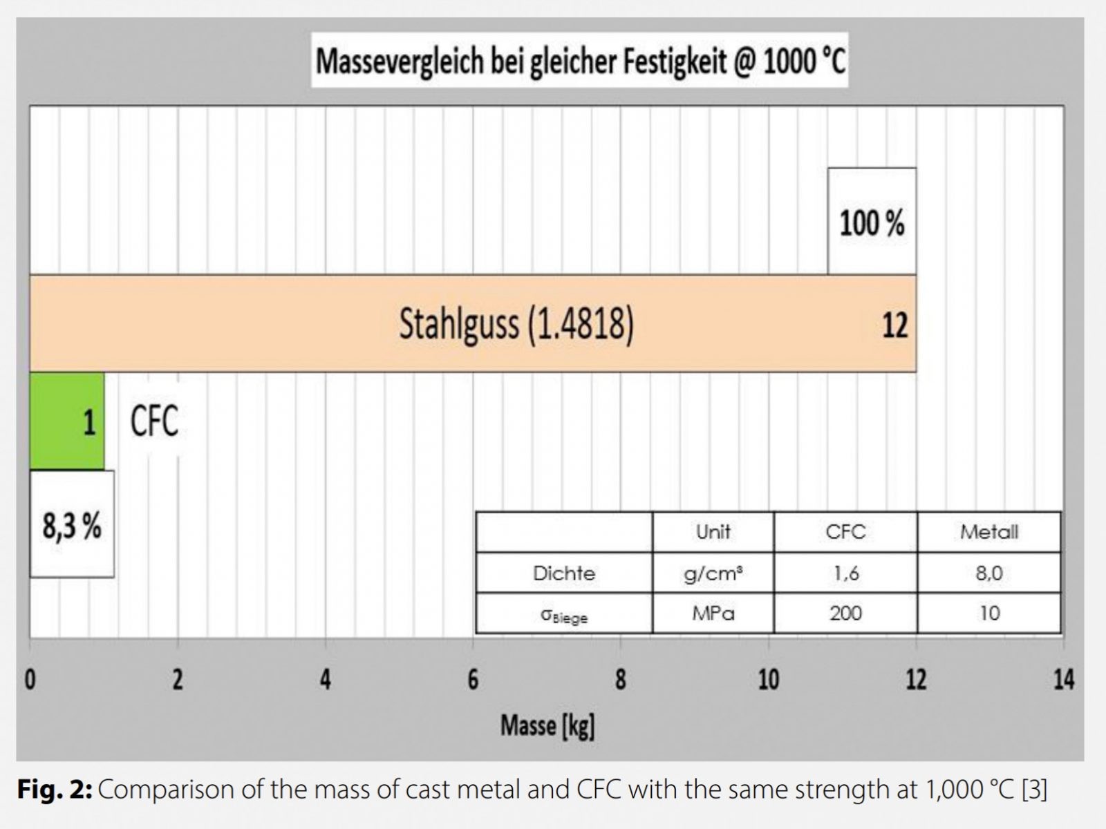
The assessment of specific strength in terms of the “load bearing capacity” of CFC and cast steel shows that, theoretically (component dependent), about 90 % of the fixture mass (“dead mass”) could be saved (Fig. 2).
Due to the lower density (CFC: 1.6 g/cm3 / cast steel: 8.0 g/cm3), the energy requirement of a CFC fixture when heated from room temperature to 1,000 °C is calculated to be about 1/5 of the comparable requirement of a cast fixture [2]. The combination of load bearing capacity and energy requirement in the CFC fixture promises a higher packing density and thus a higher furnace capacity. Compared to low-pressure carburizing with high-pressure gas quenching (N2, He), which takes place without oxygen, in the case of gas carburizing and subsequent oil quenching, the chemical degradation of CFC by oxidation is to be assessed. Above 350 °C, the CFC surface can be damaged by oxidation in air, so lowering the load bearing capacity. Based on HEAT’s own operating experience and extensive preliminary tests, a reasonable plant modification is needed at the exit of the batch. This ensures that the CFC is not exposed to any critical temperatures above 350 °C. Most oil residues are removed in the subsequent washing process. The solvent used does not affect the material. These results were a factor in the decision to use a CFC system.
PROCESS ANALYSIS AND CFC REQUIREMENTS
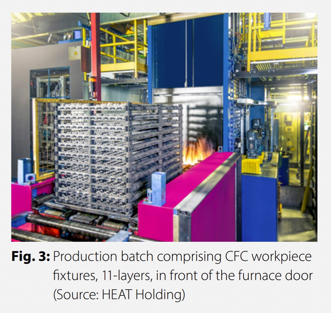
The process analysis defines the technical requirements of the CFC fixture. As a lift truck (forklift truck), connecting rods and transport chains are used for transportation, a cast base tray was selected as link (transport systems – casting – CFC). With the cast CFC material combination, the clearly different thermal expansion coefficients, particularly for the post system, have to be taken into account in the design. In a test series, the influence of gas carburizing, oil adhesion (quenching medium) to air at the chamber outlet, and the washing agent for cleaning were analyzed. The gas atmosphere and the washing process were not shown to have an effect on the material. However, with atmospheric oxygen, the unavoidable drops of oil on the workpiece fixture led to flame formation and thus to temperatures above 350 °C. With an additional measure to the heat treatment facility, this situation was reliably improved and maximum temperatures of 350 °C in air are ensured (Fig. 3).
Loading takes place at the stations already set up for this purpose. The existing infrastructure can be used without restriction for the CFC workpiece fixtures. However, Fig. 2: Comparison of the mass of cast metal and CFC with the same strength at 1,000 °C [3] Fig. 3: Production batch comprising CFC workpiece fixtures, 11-layers, in front of the furnace door (Source: HEAT Holding) 2-2017 heat processing 43 Heat Treatment REPORTS system operation is such that employees must be given the relevant training. The slim design and much lower weight initially create the impression of insufficient stability. Employee training includes handling when loading and unloading, internal transport with forklift trucks and storage on magazine stations outside of batch operation. A process description, including illustrations, is useful and is supported by the experience of Graphite Materials GmbH. Taking account of the heat treatment parameters, component costs, quantity per delivery date and process conditions, the following requirements were developed:
■ Components per batch (plant capacity)
■ Furnace loading of max. 1,500 kg
■ Usable furnace space (860 x 1,170 x 1,100 mm)
■ Cast base tray for linking the CFC grid (860 x 1,170 mm)
■ Fixture service life of min. 1000 furnace runs.
The structural design criteria are derived from:
■ Loading density (parts per layer)
■ Throughflow (heat dissipation)
■ Components loading methodology (contact surfaces)
■ Load bearing capacity (load/volume)
■ Ability to replace damaged fixture elements
■ Cast base tray: cast CFC thermal expansion.
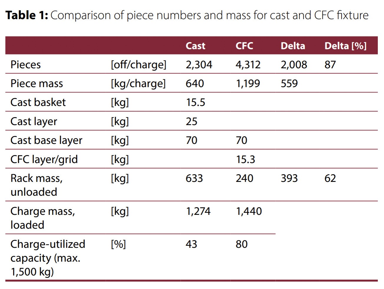
The CFC system produced is shown in Fig. 3. Compared with
the cast variant, the number of pieces can be increased from
2,304 to 4,312, namely by 87 % (Table 1).
The slim design reduces the dead mass by 393 kg. In this way, depending on the components, there is a 60 % reduction in fixture weight and this enables a larger number of pieces (packing density). The weight of the CFC fixture includes a cast base tray (70 kg). It should be noted that, due to the advantageous CFC material properties, an optimization of the cast design (baskets) was not considered. The batch volume is calculated according to the maximum weight of 1,500 kg of the furnace. The comparison between cast and CFC clearly shows that for this drive component (piece * component mass) 80 % of the furnace capacity are useable thanks to the CFC design. This corresponds to almost twice (87 %) the batch volume.
PRACTICAL EXPERIENCE
The CFC fixture has now been in use for eight months or 200 furnace runs and has proven successful. Via the link to a cast layer, the loading and unloading stations already set up could be used in full without the need for any additional input. Staff were trained and the plant was subsequently commissioned. Due to the much lighter layers (Table 1: 15.3 kg), employees were on board from the start and carefully integrated the system in the process. The physical strain on employees is much lower, concentration improves and there is a lower risk of injury. CFC is almost distortionfree (3) with the result that the component loading remains unchanged in the position and form compared with the virgin state of the CFC layer (Fig. 4).
The components sit reproducibly in a fixed position in the layer. There is no risk of jamming due to the distortion of the fixture. Loading and unloading is accelerated and can be standardized by means of a semi or fully automatic procedure. Due to the higher packing density the heating, quenching and tempering processes are slightly longer for CFC loading. In this case, the number of pieces prevails over the different energy requirement compared with cast. The dwell time in order to achieve the case hardening depth (CHD: approx. 1.2 mm) remains constant, independent of the component. However, overall, the process time for the total number of parts (5 million pieces) is reduced by 50 % to 14,000 h. Due to the solid component cross section, component distortion as a result of heat treatment is not critical. However, the lack of distortion of CFC is a key advantage for the reproducibility of heat treatment. The layer does not have to be turned around in order to correct bending and can only be used adequately due to the post system. This excludes the possibility of a malfunction. The structure is designed to enable the replacement of damaged elements. Individual layers were damaged in an accident. The components affected were dismantled by the fixture manufacturer and replaced with new elements. The stability and functionality of the repaired levels have been completely restored. In principle, industrial practice with CFC workpiece fixtures shows that professional staff training, including repeated training of temporary employees, is essential for successful operation. The negative aspect of the slim design is a greater susceptibility to impacts. Careless transportation or setting down are the most frequent causes of damage. However, as a rule, the much simpler and easier operation improves employee satisfaction and this, in turn, leads to more careful handling.
CONCLUSION
The weight saving when using CFC rather than cast fixture materials is significant, however, it depends on the components loaded. In this example, the fixture mass can be reduced by approx. 60 %. With CFC, the material properties load bearing capacity and stiffness can be used for a slim design enabling higher packing density. With the same fixture basic dimensions and chamber height, 559 additional components can be processed per furnace run and the oven capacity increased by 87 %. The greater capacity reduces the total process time for the customer order in this example by 50 %. The lack of distortion of the workpiece fixture facilitates loading and unloading and the reproducibility of the treatment results. Simplified handling procedures, particularly thanks to weight savings and lack of distortion, increase employee satisfaction, occupational health and safety and support process reliability. The effects of the CFC fixture described here create benefits for the industrial partner and these can be measured in terms of an increase in added value. We would like to thank Marco Liebsch and Frederic Stackfleth, both from Gruppe HEAT, for their outstanding support.
Did you like this article? Click here to subscribe to The Monty.
Have surplus equipment? Click here to get help selling it.


