
A Guide to Trouble Shooting the Nitriding Process
Introduction
The nitriding process is perhaps one of the most misunderstood thermo-chemical surface treatment processes that are practiced today. The process of nitriding is just one hundred and sixteen years old in 2019. The patent for nitriding was first granted to Machlet of Elizabeth New Jersey in the year 1908, followed by Adolph Fry of Germany in the early 1920's. So the process is not as old as, for example carburizing. However, it is perhaps (as far as chemistry is concerned) one of the most simple of all of the thermo-chemical surface treatments are concerned. We will describe in this article some of the problems that can occur as a result of and during the nitriding process.
There are many problems that can occur with the nitride procedure, and it will be necessary to evaluate the process technique. The process techniques can be described in the following illustration:

The next illustration shows the process techniques of nitriding with the process mediums and the operating temperature range


From this , it can be said that the trouble shooting can be categorized into three very distinct categories which are shown as follows: (Fig 3)

Referring back to Fig 1, we will deal with the problems usually associated with process problems
Gas Nitriding
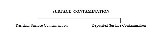
One of the major problems with gas nitriding is the understanding of surface preparation in terms of surface cleaning. It cannot be over emphasized, how important the pre-cleaning of the surface of the steel is. Surface cleanliness in mandatory and a primary requirement to the success of the procedure. Surface contamination can be seen in many forms Fig 4. Once the surface contamination has been dealt with prior to the nitriding process, then we can deal with the problem occurring at the nitride procedure.
Case Flaking
This can occur as a direct result of the presence of a surface contaminant on the component. Investigate the pre- cleaning method prior to nitriding and after pre-machining.
Case Crushing
This problem is usually due to a low core hardness that is failing to support the nitrided case. Another possibility is that the formed case is too shallow and this can be remedied by increasing the case depth. However the increase of case depth should be cautioned. Check what the application of the work piece is and what sort of load will be applied to the component
Salt Bath Nitriding.
Salt bath nitriding can be an economical method of nitriding providing that both the salt bath chemistry and the salt bath cleanliness are maintained. It is mandatory that the salt bath chemistry is checked at the commencement of each shift and the appropriate additions of salt are added to return the bath to its operational strength.
Regular desludging of the bath is necessary, to remove precipitated oxide in suspension in the salt, from work baskets and suspension wire.
Pre cleaning is as mandatory as it is with the gas nitride procedure, and most importantly after the nitride treatment, to remove any trace of the heat treatment salt in holes or cavities.
Dilution Nitriding
Dilution nitriding is a process that has been known since the initial development of gas nitriding by Adolph Machlet. The process has been refined and developed in North America to a very precise science and it is a process that still uses ammonia as the nitrogen source but controls the surface metallurgy of the procedure by dilution of the process gas using nitrogen or hydrogen. The next area of process control and process repeatability is to deliver the process gas in a very precise gas metering system.
The problems that can occur are mainly due to the metallurgical aspect of the procedure such as are described in the gas nitriding section. The problems are not usually hardware or program related, although there is no doubt that problems can ultimately occur.
Ion Nitriding
Ion nitriding is also known as glow discharge nitriding or plasma nitriding. The process is gaining a great deal of popularity in North America due to legislation on process effluents, European engineering specifications and a growing awareness of the repeatability and metallurgical consistency of the process is accomplished by computer control. It is necessary to understand that there are two power system types:
- Continuous DC Power
- Pulsed DC Power
From this there are two types of hardware system which are:
- Cold Wall
- Hot Wall
Part Overheating
This is usually as a result of the parts being too close together and is known as Hollow Cathode Effect. The hollow cathode effect can usually be seen during the process if one looks through the process sight glass. The particular area being subjected to the hollow cathode effect can sometimes be seen to be glowing at a visible temperature. It can also be seen after the process is completed and the part unloaded from the process chamber, as a dark area on the part where the hollow cathode has occurred. It can also be measured in terms of hardness. That area of the part will be lower in surface hardness than the rest of the component.
The part can also be over heated by process voltage and amperage variations during the process. This can be caused simply by an incorrect program process value being used in either the process controller or the PC (if the process control is by PC). The overheating could also be caused simply by an incorrect temperature value being used.
So what is the correct process temperature to use? This will depend on:
- The steel composition that is being used for the part manufacture
- The pre-heat treatment tempering temperature
- The surface metallurgy that is required
Avery important aspect of non-uniform process temperatures during the nitride procedure and in the process chamber is that it will cause case depth variations on the component. Therefore the loading of the process chamber is extremely important to ensure that hollow cathode does not occur. Further to this, it is important that the process thermocouples are placed in the load area that will present an accurate picture of the process temperature on the part surface. It is equally important that the process control; values are values that are known to be 'good values' from previous runs.
Loss of Nitriding
If, during the observation of the process conditions through the furnace sight glass, there are area's on the part being treated, that there is no plasma glow sitting uniformly around the component, it simply means that the selected process pressure is incorrect and that the value is too high. If this condition occurs, it is most important to rectify the condition, because where no glow is seen on the component, no nitriding effect will be taking place, which further means, no case formed or at least a very shallow case will be formed. The manner in which this condition is corrected, is simply to check that there are no leaks on the vessel (remember, the process is operating at partial pressure conditions), or if no leaks, reduce the operating pressure setting. Until the glow seam reappears on the part, the parts are not previously covered by the plasma glow seam and will not be nitrided.
Arc Discharge
This is usually seen on continuous DC current systems, but can also occur in the pulsed DC systems (although not too frequently on the pulsed power system). The cause is from too high a process voltage, so the remedy would be simply to reduce the process voltage until the discharge no longer continues to occur. The arc discharge is simply seen as a miniature 'lightning strike' in the process chamber and will usually be attracted to sharp corners on the component, which will result in localized overheating and probable surface burin/localized melting. The remedy is simply to reduce the process voltage, or change the process pressure.
Part Chipping
This is usually seen, once again at sharp corners. The most probable cause is 'nitride networking'. This means that the corner that has chipped has been over saturated with nitrogen. This condition can apply also to gas nitride and salt bath nitride. The cause is, that too much nitrogen is present in the corner due to the 'corner effect'. Nitrogen is soluble in iron up to a value of approximately 7% by volume (maximum). When over saturation occurs, the nitrogen has precipitated out of solution during the cooling stage of the process and has settled at the grain boundary locations in the corner if the component. The remedy is simply to reduce the nitrogen in the process, or round off the corners of the component.
Low surface hardness
This can be caused by a low nitrogen availability with insufficient nitrogen in solution with the steel to form sufficient stable nitrides in the surface of the steel. Another condition that can cause this is that the steel itself is too low in nitride forming alloying elements. The remedy is simply to change either the steel that the component is manufactured from, or increase the nitrogen and thus the nitride potential of the process gas.
Surface Flaking
The cause of this condition is usually due to a surface contaminant being carried into the process on the part surface. Simply check the manufacturing method for the type of coolant or cutting fluid used during the pre-machining operation, and then check the method of pre-cleaning prior to the nitride procedure. Some surface contaminants can be removed by sputter cleaning at the commencement of the ion nitride process using hydrogen as the sputter clean gas. If hydrogen is not aggressive enough, then a blended mixture of hydrogen/ argon can be used. However be cautious with the use of argon as this gas has a high atomic weight and can cause surface etching. The maximum suggested volume of argon would be 10% argon with 90% hydrogen. Generally the mixture ratio is 5%argon and 95% hydrogen
Sincerely David